USB firmware of CDC and HID for PIC18F2550, PIC24FJ64GB002
<< Reference >>
Microchip Libraries for Applications (MLA) v2014_07_22
<< My two boards >>
1) My UBW board with PIC18F2550 (in my page on Jan. 16, 2014) works as a USB device.
A configuration of CONFIG1L register of a USB bootloader is set to “Divide by 5 (20 MHz oscillator input) and 96 MHz PLL divided by 2 to derive system clock”, so Fosc is 48MHz derived from a primary oscillator using a 20MHz ceramic resonator.
LED : RC0, RC1; Switch (pull down) : MCLR, RC2;
LCD (SC1602BBWB-XA-GB-G) : RS – RB2, R/W – GND, E – RB3, Data bus – RB4~RB7;
USART : RC6 for USART_TX, RC7 for UART_RX;
2) My board with PIC24FJ64GB002 (of my page on Aug. 31, 2014) works as both a USB device and a USB host.
FRC 8 MHz – 96 MHz PLL;
48 MHz for USB Module (96 MHz PLL divide by 2);
32 MHz for System Clock (96 MHz PLL divide by 3);
LED : RB0, RB1; Switch (pull down) : MCLR, RB2;
LCD (SC1602BBWB-XA-GB-G) : RS – RB7, R/W – GND, E – RB8, Data bus : DB4 – RB9, DB5 – RB13, DB6 – RB14, DB7 – RB15;
UART : RA0 for U2RX, RA1 for U2TX;
<< USB Device : CDC (Communication Device Class) Serial Emulator >>
It is necessary to select the appropriate configuration in the project of MPLAB X IDE when compiling by XC8 for PIC18F2550 or XC16 for PIC24FJ64GB002.
<< USB Host: CDC >>
No picture.
Code for my board with PIC24FJ64GB002 :
<< USB host : HID (Human Interface Device) class >>
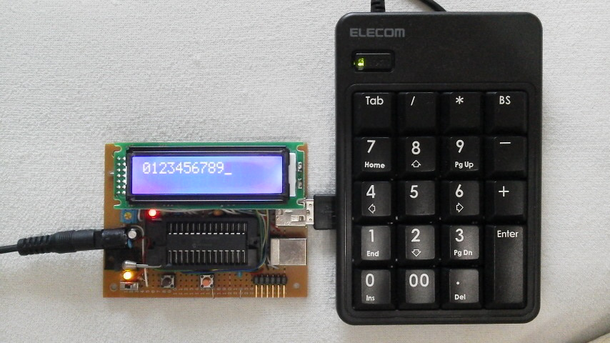
Code for my board with PIC24FJ64GB002 (outputting a ASCII code translated from a HID code) :
<< A demonstration >>
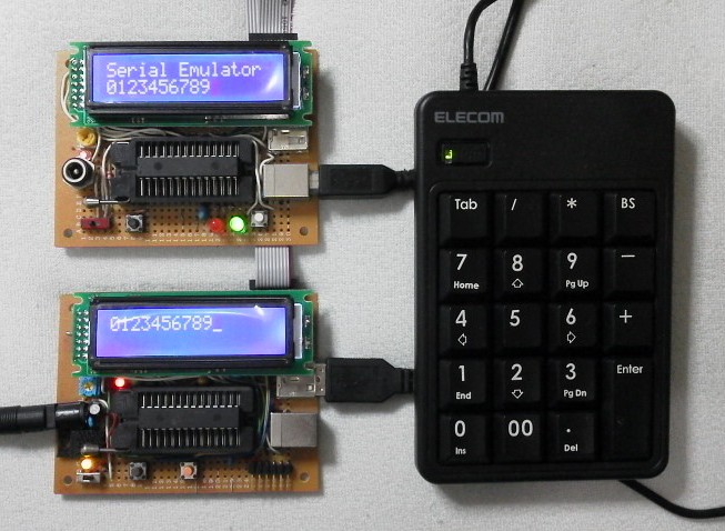
Keypad – USB – Host (24FJ64GB002) – UART – Device (18F2550) – USB – PC (terminal soft):
The upper board (PIC18F2550) practices a USB serial emulator and the lower (PIC24FJ64GB002) does a USB HID. A PC (terminal soft) is not shown in the above picture.


