PIC18F27J53 equipped with a USB bootloader
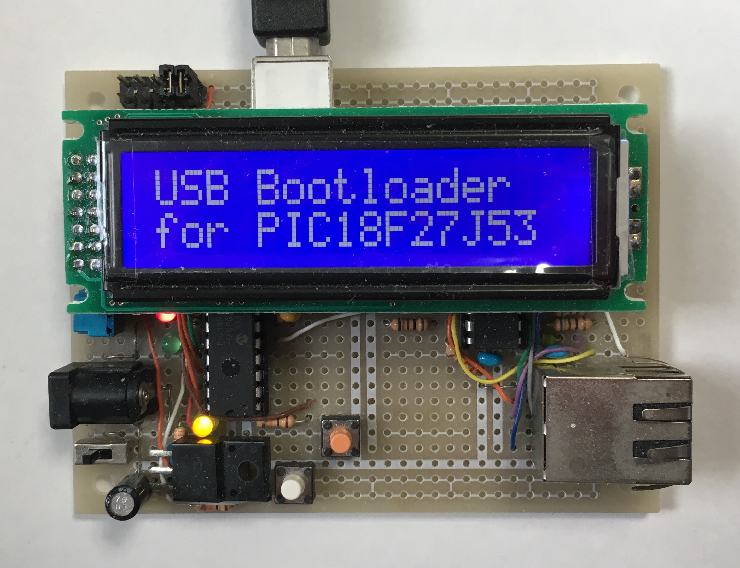
The PIC18F27J53 board equipped with a USB bootloader
The above Ethernet board was previously reported in my page on Apr. 23, 2017.
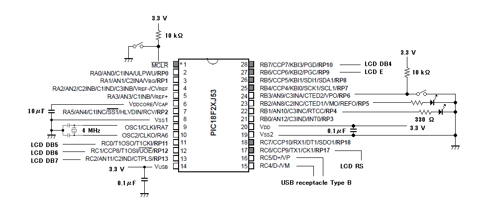
Clock and pin connection of PIC18F27J53 :
The system clock of 48MHz is derived from the external ceramic resonator of 4MHz using the PLL module.
LED : RB1, RB2; Switch (pull down) : MCLR, RB3;
LCD (SC1602BBWB-XA-GB-G) : RS – RC6, R/W – GND, E – RB6, Data bus : DB4 – RB7, DB5 – RC0, DB6 – RC1, DB7 – RC2, VDD – 5 volt;
The basic circuit of my board equipped with the PIC18F27J53
<< USB Bootloader code >>
When you compile this code by C18 on MPLAB X, you must include the linker provided for HID Bootloader by Microchip Technology.
<< LCD display code for the USB bootloader >>
A code for a USB bootloader must be compiled at the code offset, 0x1000, with the linker provided by Microchip Technology .


