LC meter using PIC18F2550
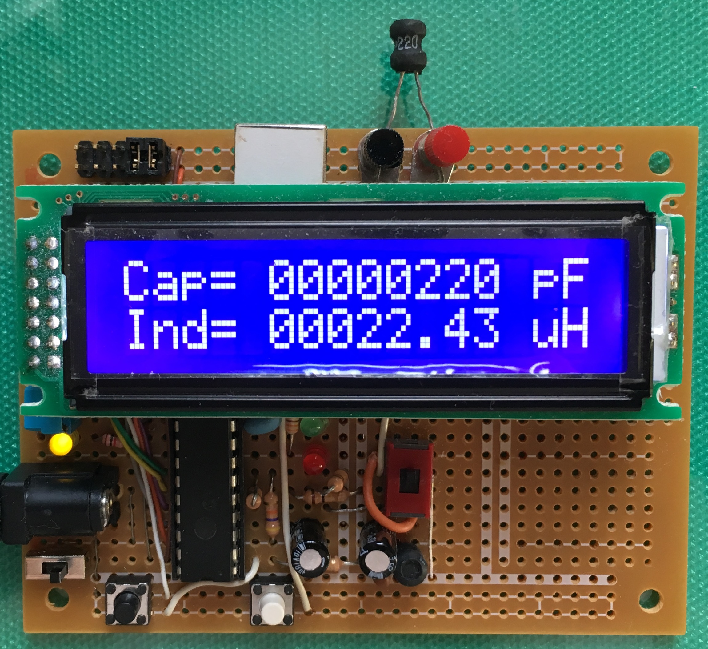
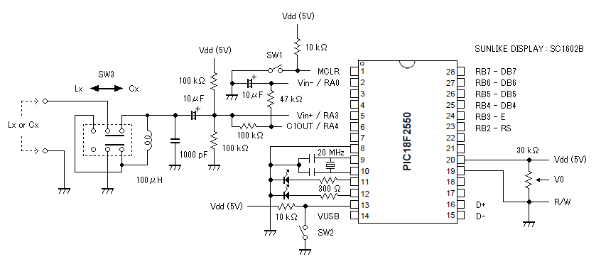
I assembled a LC meter using the PIC18F2550 by referring to previous reports. Capacitance or inductance is derived from parameters of the Franklin oscillator, which is built of a comparator of the PIC18F2550. Measurement is not accurate but is enough to use for my hobbies.
<< Introduction in Japanese >>
PIC マイコンを用いたコンデンサの容量、コイルのインダクタンスを測定する LC メータを作成した。ネットで検索すると PIC マイコンを利用した LC メータの制作記事は容易に見つける事が出来る。測定精度はホビー・ユースに於ける概算程度と思って良い。発振回路の周波数を測定する際のゲート時間を 0.1 秒に設定しているが、検体のキャパシタンスやインダクタンスが大きくなると、発振周波数が小さくなり、短いゲート時間で測定する周波数にも誤差が大きくなる。また PIC マイコンによる演算精度にも制限があるため、算出精度に過大な期待は出来ない。
<< Measurement >>
Measurement of capacitance or inductance can be selected by the slide-switch.
Set an object to terminals.
After powered up, the system is going to start measurement.
<< Calibration >>
- Remove an object from terminals and set SW3 (slide-switch) for “capacitance”.
- While pressing the SW2, reset the system by the SW1. Then the procedure of calibration starts.
- When a frequency proper to the board is stable, release the SW2.
- After setting a reliable capacitor of 1000 pF to terminals, hold the SW2 on.
- When a frequency is stable, release the SW2.
- After removing the object and set SW3 (slide-switch) for “inductance”, hold the SW2 on.
- When a frequency is stable, release the SW2.
- After calibration is completed, the system dose the routine of measurement.
<< 使用法 >>
測定は電源を入れて検体を端子に接続するだけである。
<< 定数の校正と EEPROM への保存(キャリブレーション)>>
1 検体を取り外す。スライド・スイッチ (SW3) で「コンデンサ」を選択。
2 SW2 を押しながら SW1 でリセット。
3 SW2 押した状態を維持。発振周波数 Fcap が安定したら SW2 を解放。
4 校正用コンデンサ 1000pF を端子に装着。
5 SW2 を押した状態を維持。発振数波数 Fobj が安定したら SW2 を解放。
6 スライド・スイッチ (SW3) で「コイル」を選択。端子間をリード線で短絡する。
7 SW2 を押した状態を維持。発振周波数 Find が安定したら SW2 を放す。
8 検体測定の main loop に戻る。
<< Sample code >>
(compiled with MPLAB X IDE and XC8)The PIC18F Peripheral Libraries needs to be installed into the XC8 compiler to use EEPROM.
<< Reference >>


